This QNAP model TVS-871 is similar to the TVS-471, TVS-671 and the TVS-871T. The disassembly will be slightly different, but this guide could still help you disassemble the unit.
Before we disassemble the unit, make sure you got a long Phillips screwdriver (crosshead). Otherwise you will not be able to remove the SATA board tray out. What you need is:
- Long Phillips screwdriver
- CPU and Thermal paste (optional – for replacing CPU)
- RAM (optional – for replacing old RAM)
- 4 hours of your time
- Invalidating your warranty, if you had any.
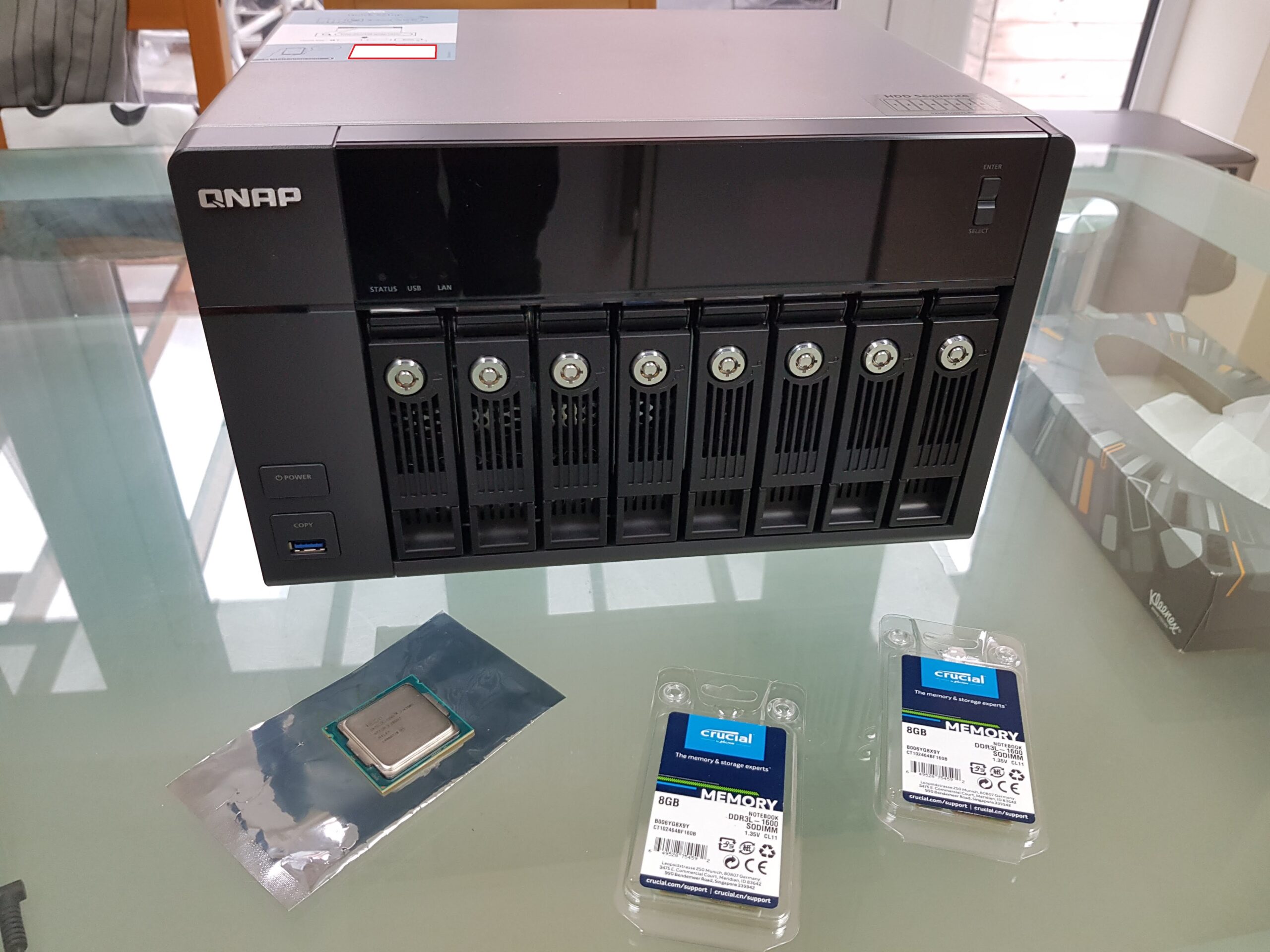
First the CPU, I got myself the Intel Core i7-4790S which matches one of the CPU model used in the highest specification for this TVS-871 that QNAP approved. You can try other Intel Haswell CPU with socket LGA 1150, but look at the TDP if it’s higher than 65 W you probably wish to upgrade the fans or change the heat-sink (May not be possible looking at the design and shape of the heatsink).

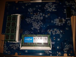
The maximum RAM configurations is 2x 8GB to make 16GB, yes the Intel specification states that the Haswell CPU can handle 32GB but that is using 2 memory channels, such as 4x 8GB to make it 32GB, this unit has only 1 memory channel.
I got myself 2* Crucial 8GB CT102464BF160B DDR3L 1600MHz SODIMM to maximize the RAM availability on the unit.

Remove all the drive caddy out of the system, but make sure you label which drive goes into which bays. Otherwise your QNAP will not boot correctly.
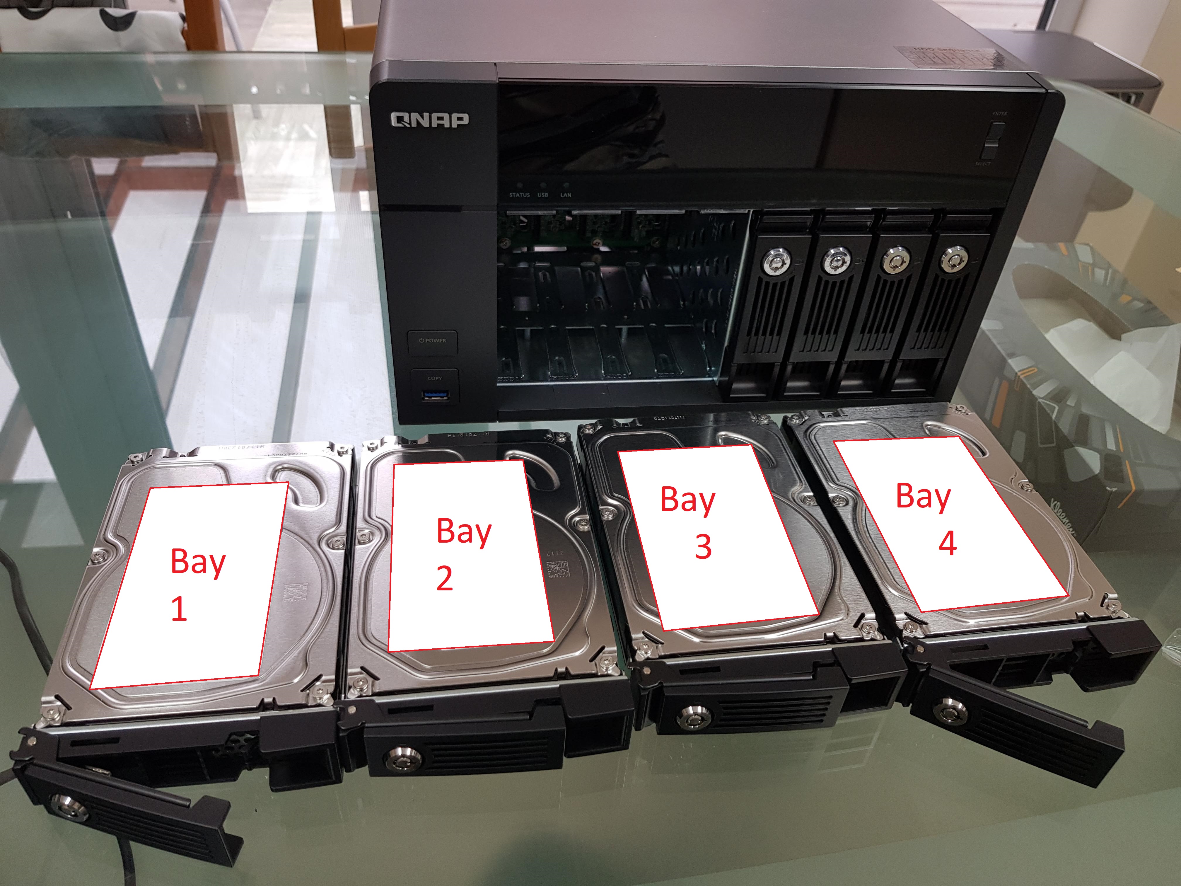
All the caddy removed.
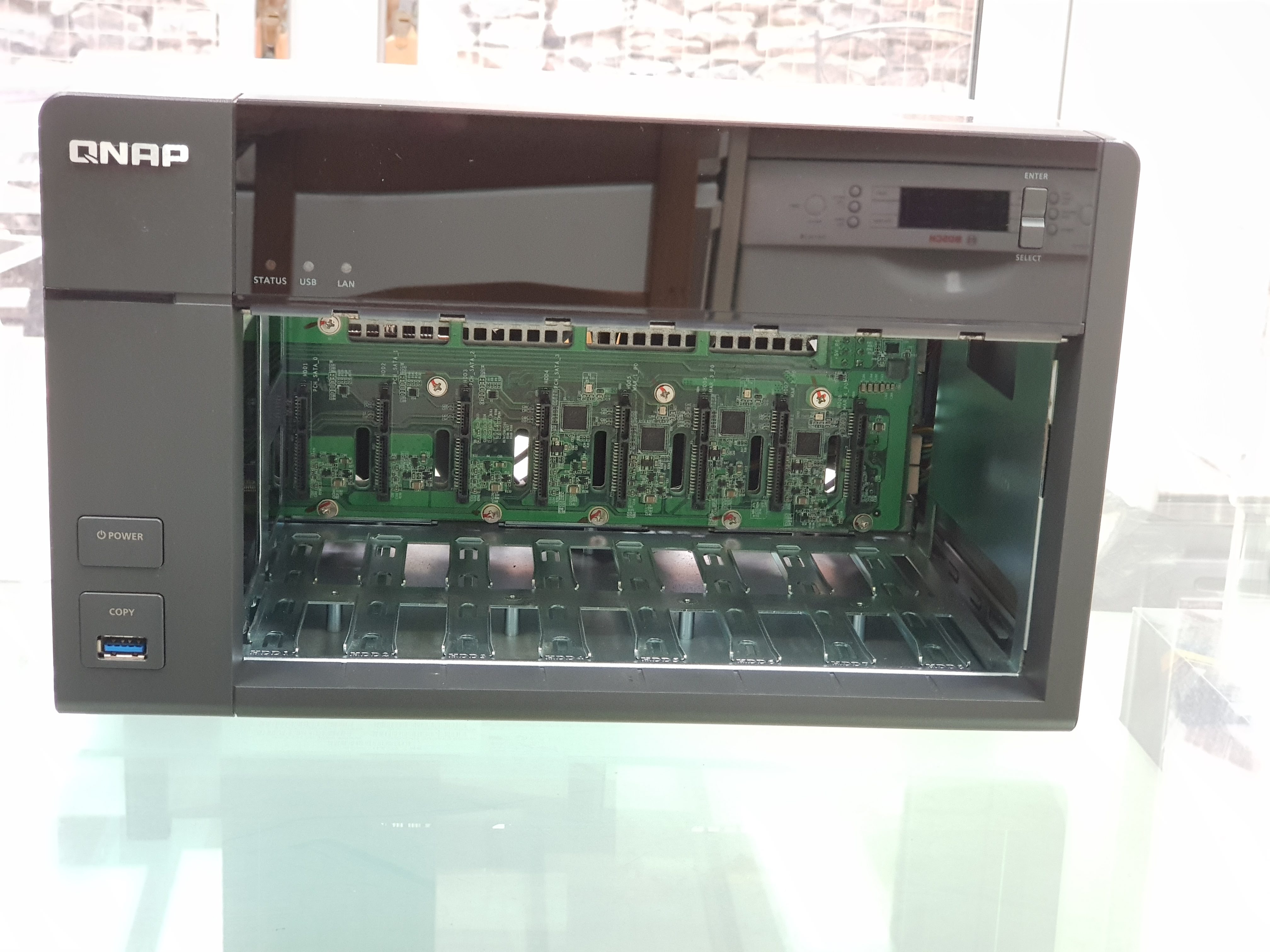
Remove the 6 screws for the outer top casing.
You should be able to pull the lid away from the front, and be able to lift the cover away from the unit. It’s fine to flex the cover off, it’s only made of metal.
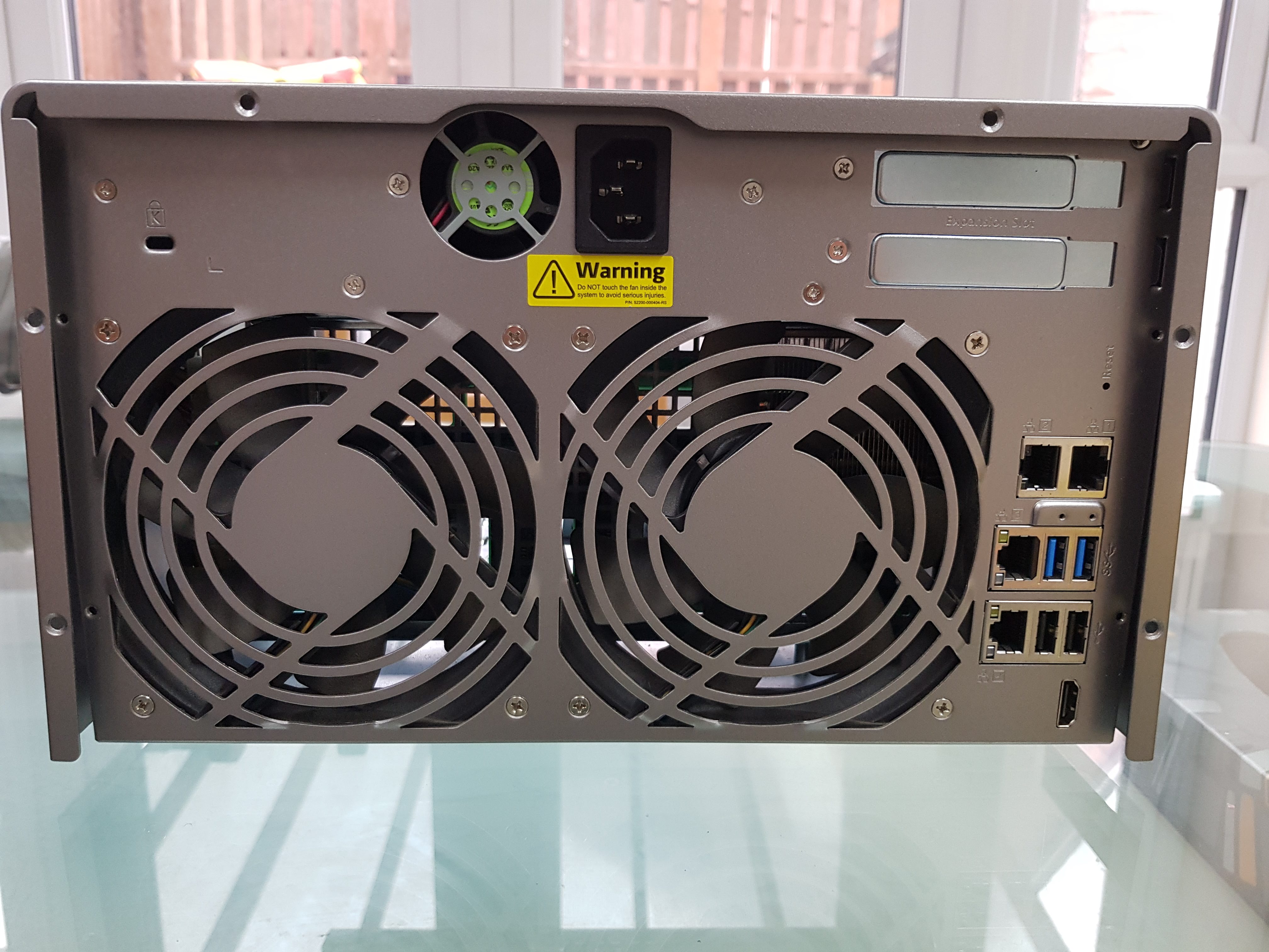
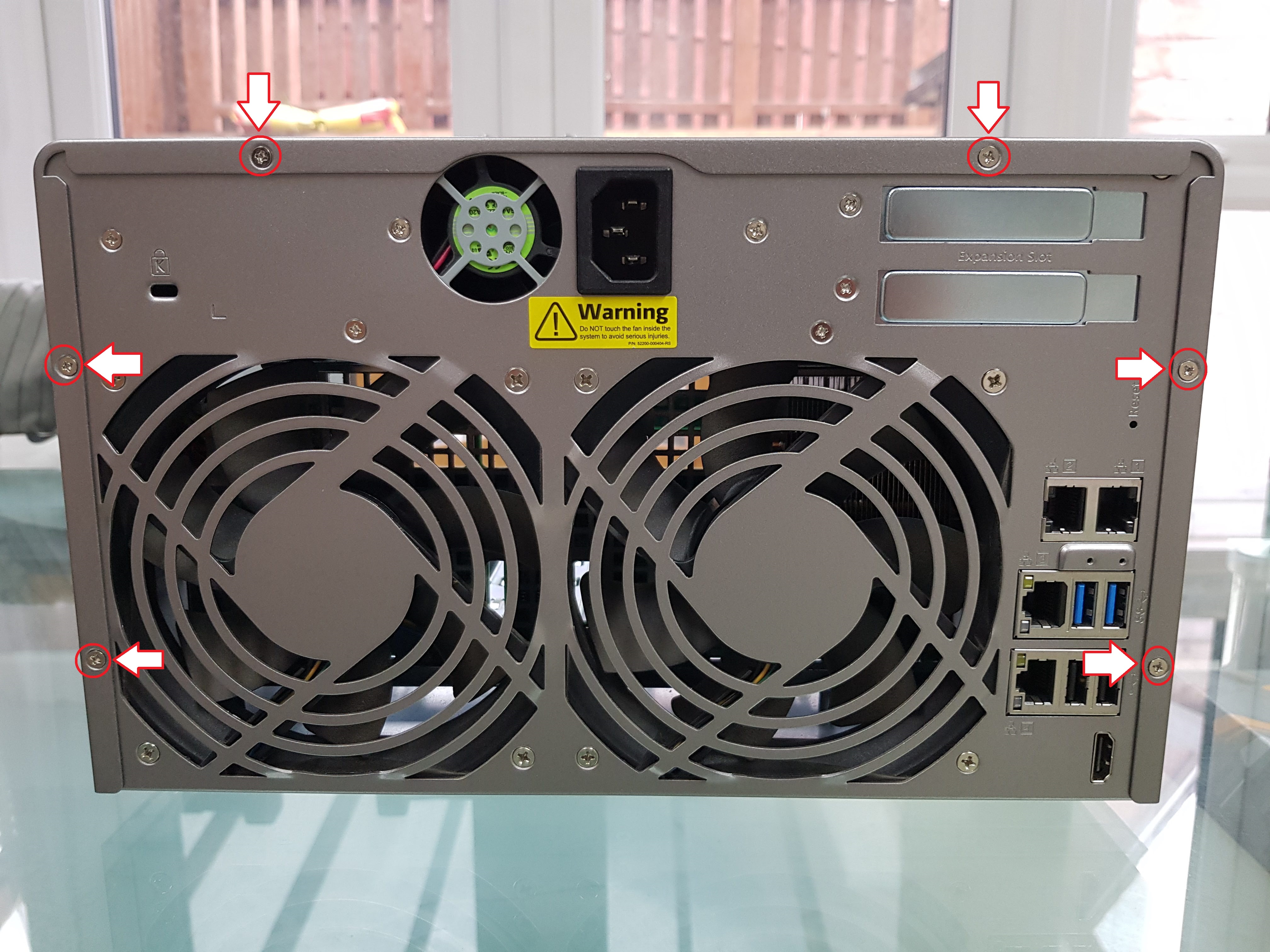
Time to take the rear back panel off, remove 1 screw on the left side corner on the unit.

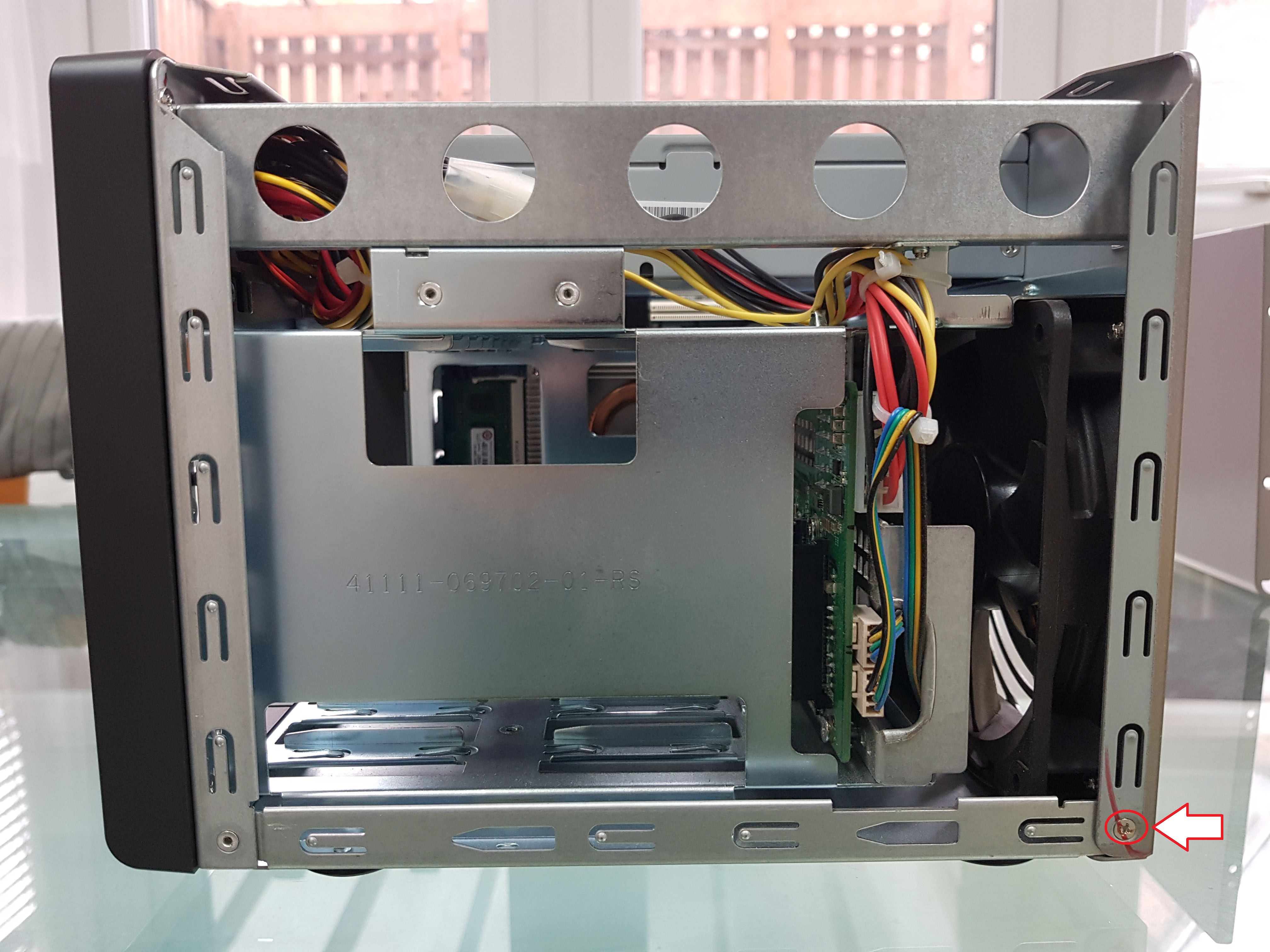
Remove the other 1 screw on the right side corner of the unit.
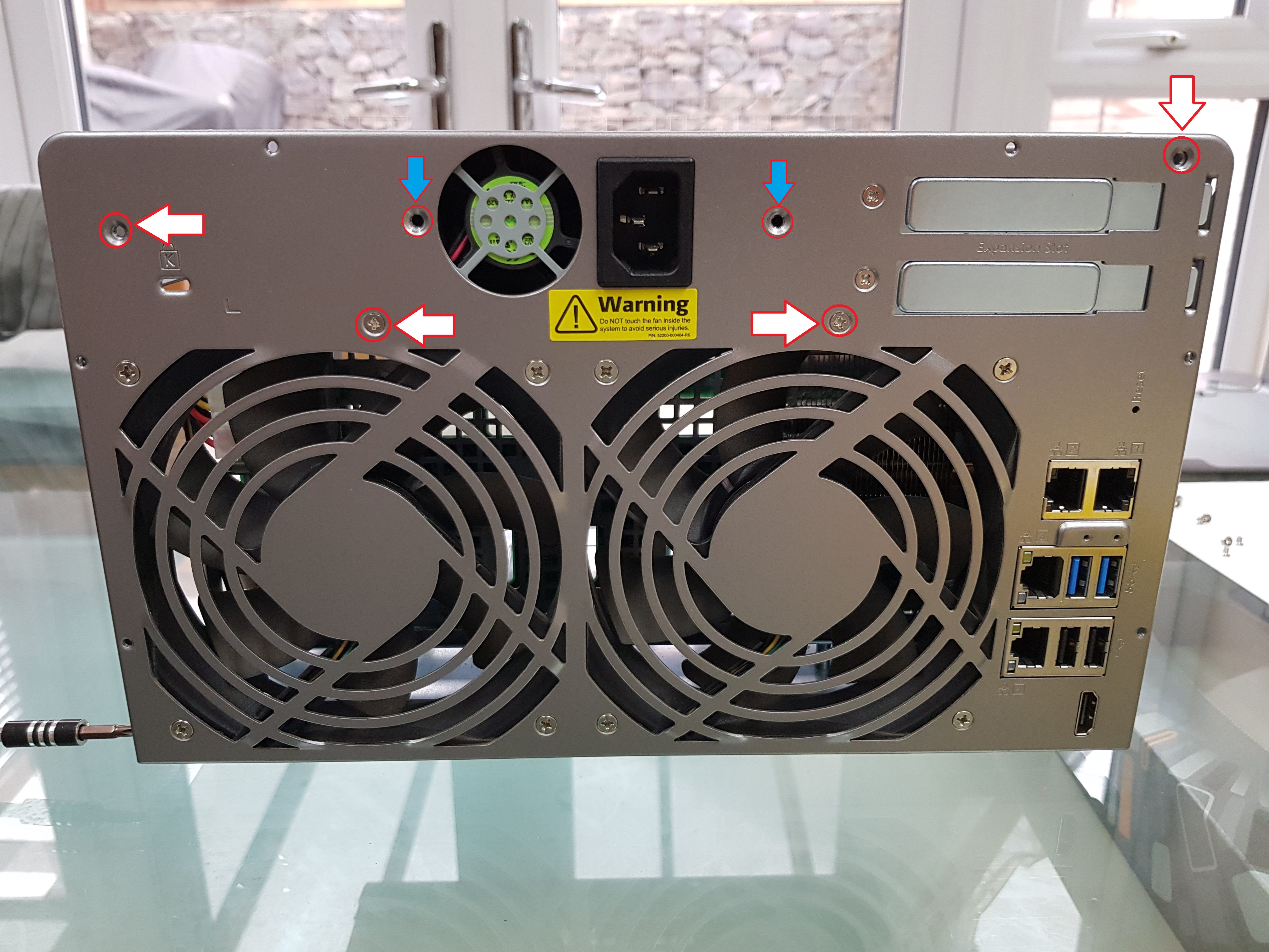
Please note that the 2 rear PSU screws are different to the other rear screws, put them separately. Remove the 4 chassis screws.
3 more screws are underneath the unit

You can then remove the back panel by tilting it towards you and carefully move the panels way from the ports. We then need to remove the FAN connector for the next step so don’t remove it fully.
Please note that if you got anything installed in the PCI-E slots make sure you remove them before removing this panel.
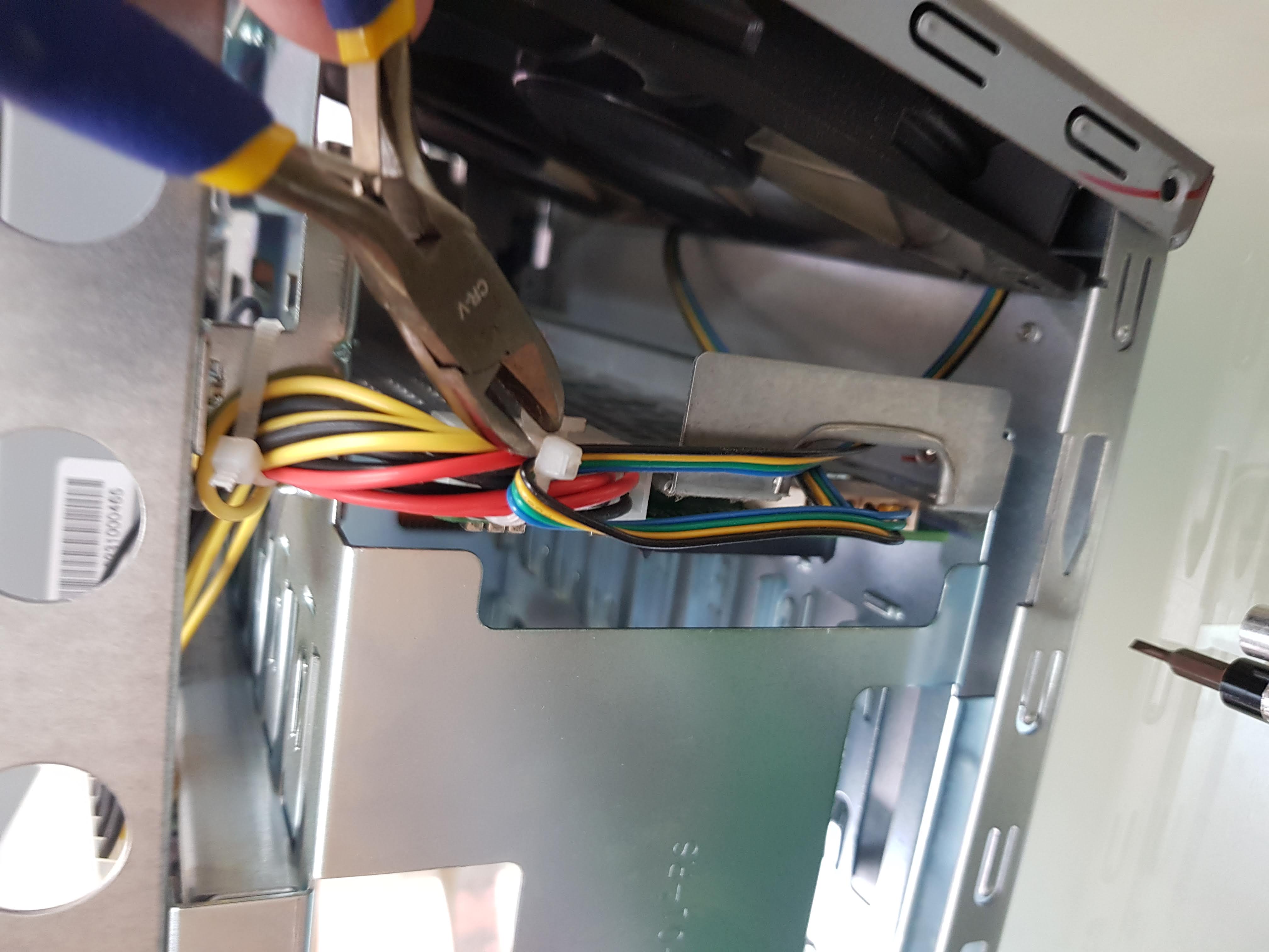
Cut the cable tie that is holding the fan cables.
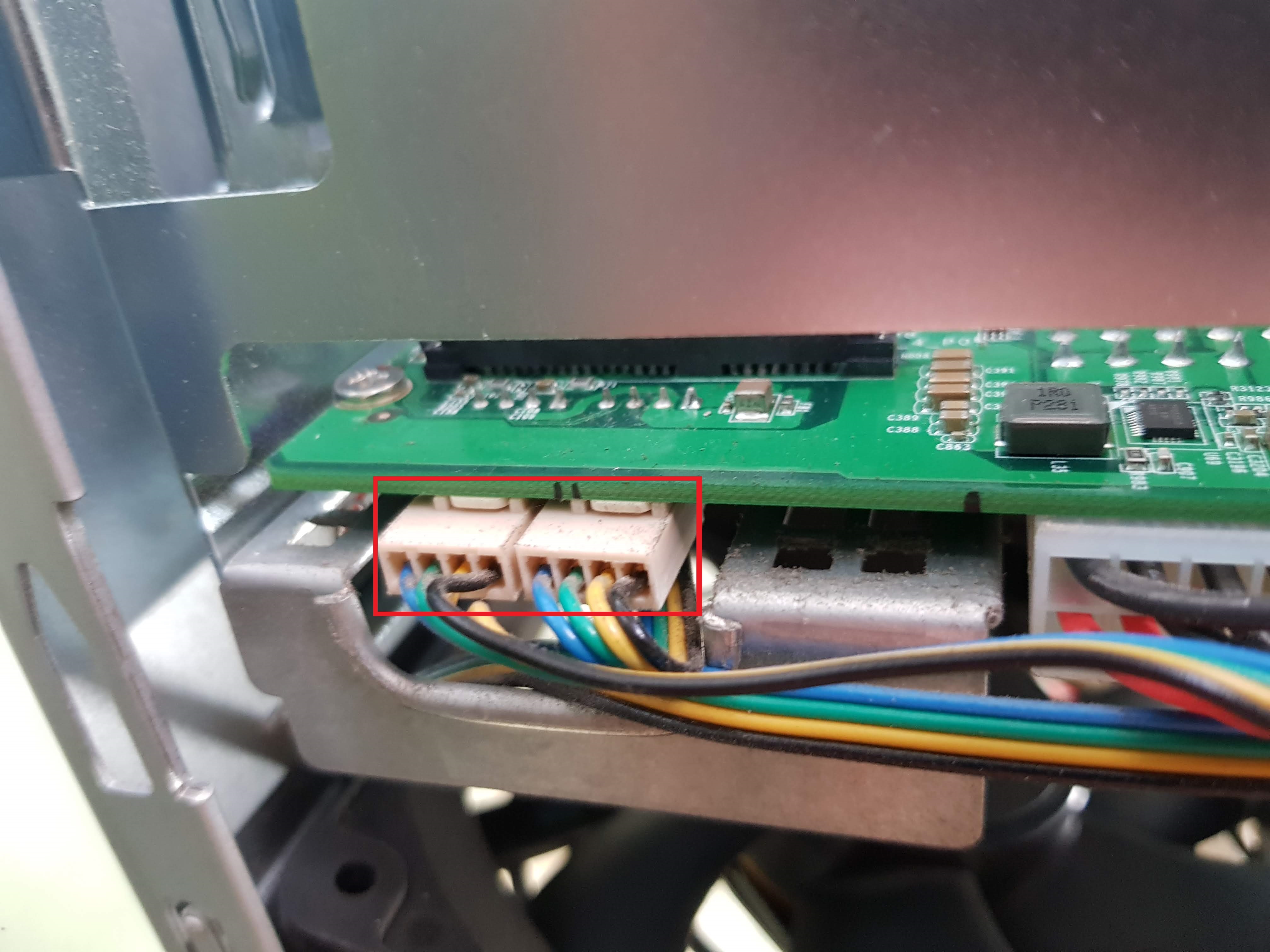
Pull the two fan connectors out, by moving the connector side to side to slowly remove them.
The whole rear back panel is now off, you can service your fan, possibly change them if you wish from this step.
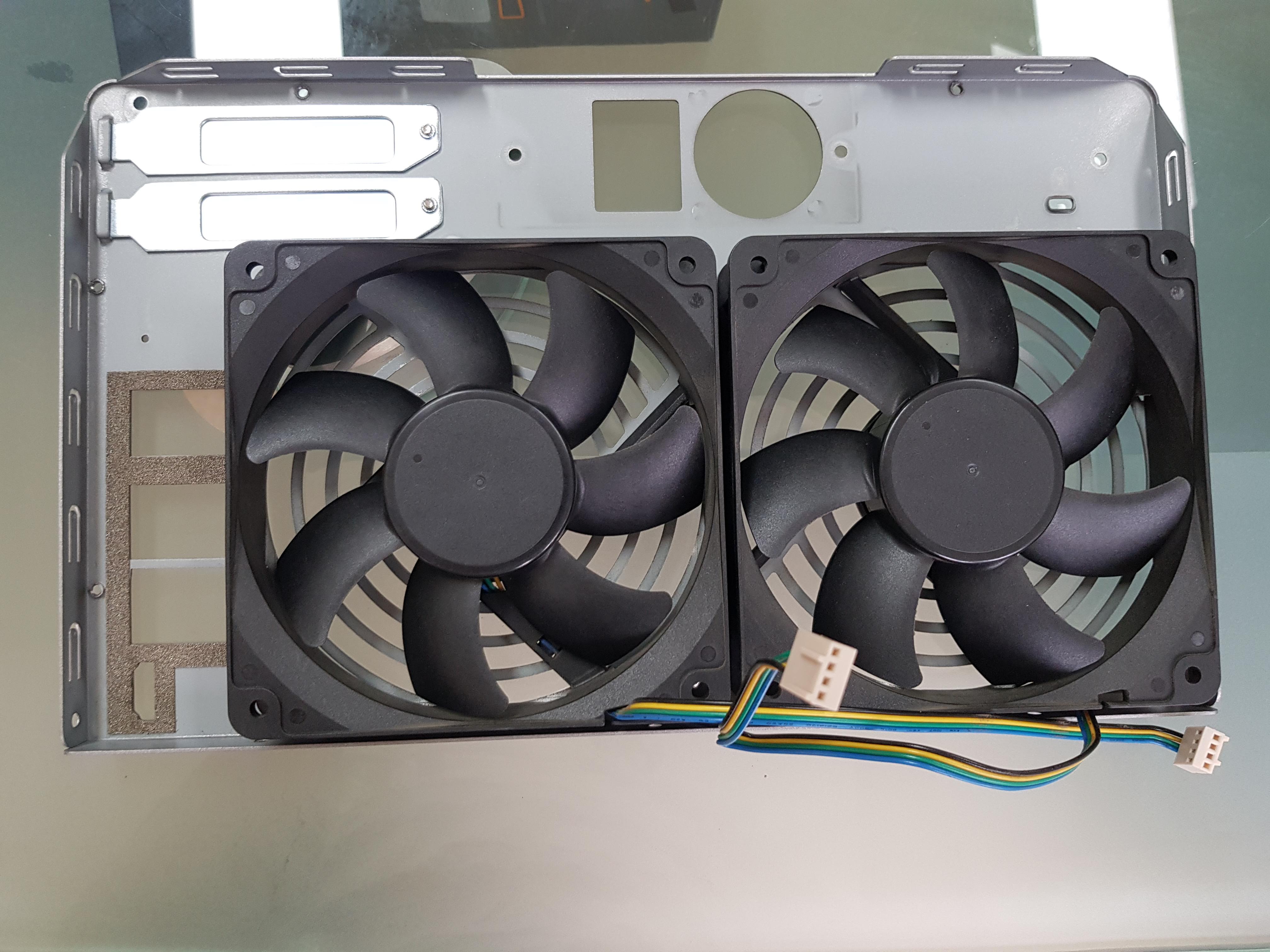
There is only 4 screws holding the fans at this point, here is the fan removed.
Y.S Tech, DC Brushless fan, FD121225LB DC12V 0.18A

The next step is to remove the power supply.

There is only 2 more screws to completely remove the power supply, they are kinda hidden by the cables near the front.

Be careful in removing the screws and to not pinch the wires of the power supply.

Same goes the other side.

The storage power connector must be removed, you have to turn it around to find the latch.

Ensure you push the latch out of the way when pulling the connector off.

Disconnect the LED screen connector and the ATX power connector, make sure the latch of the 24-pin connector is out of the way and as you pull the connector you have to tilt it out the way of the storage cage.

Can be fiddly to get this cable out.

(Optional) I’ve notice the LED ribbon cable is damage due to the sharp edges of the casing, just taped it up to avoid any more damage.

You can use cloth tape, or electrical tape.

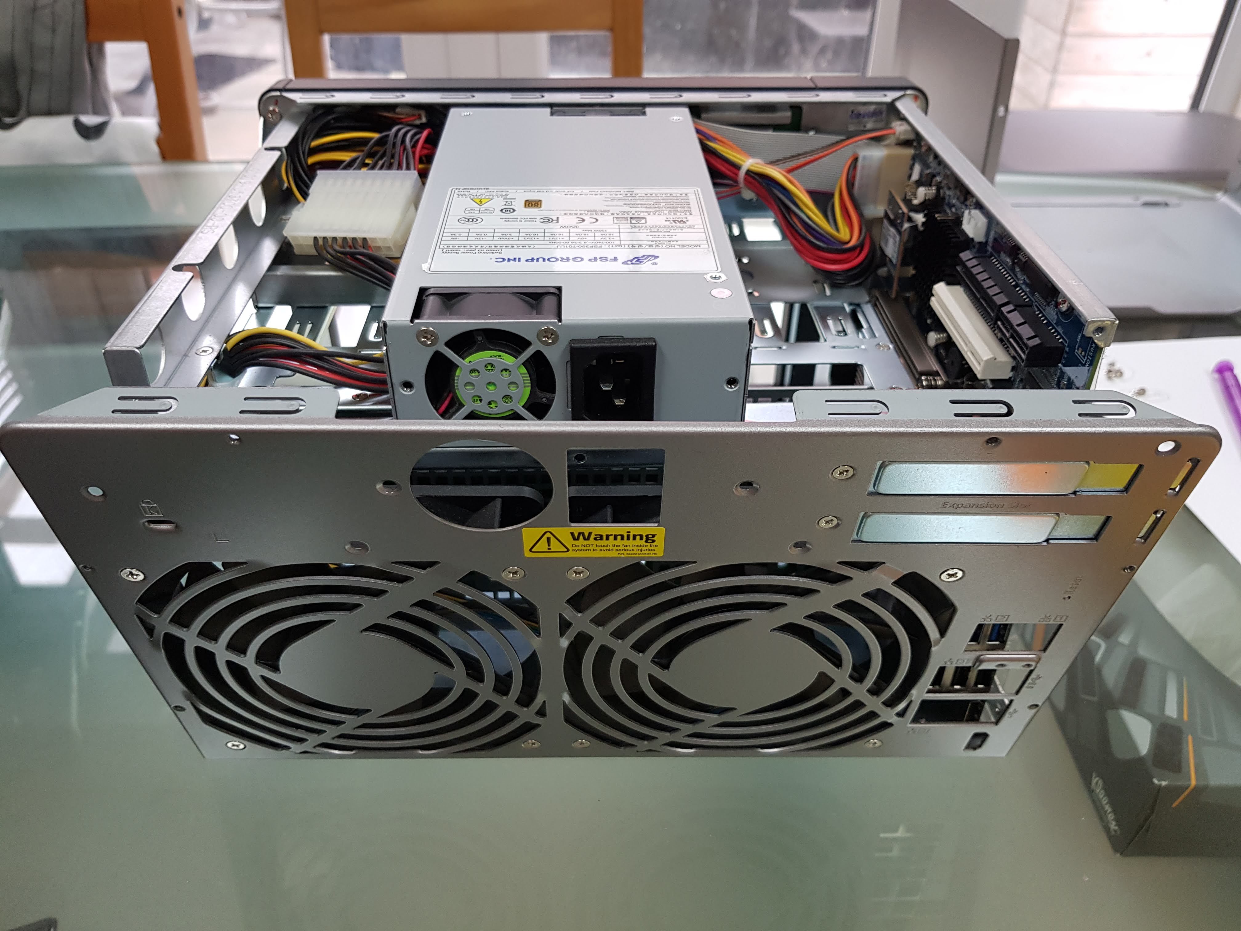
The power supply should now be removed, this is an FSP FSP350-701UJ 350W PSU.

Next we need to move the storage power connector out of the way, you must cut the cable tie. For you to be able to move it to the left side of the case.


Once you moved the cable out, we can start removing the 5 screws for the SATA board tray.

You really need a long screw driver to reach the bottom right screw.

Likewise for the left side screw, but this side is tight and it’s harder to put through with attachments.

Now you can pull the whole SATA board tray, slowly ease it out of the connector when doing so.

Doesn’t matter if the power extension cable is still attached.


Rear view of the SATA board tray.

Still need to take the front panel, LED board and then the motherboard to reach the CPU.

To remove the front panel, you have to remove 3 screws on the right side.

And again on the left side.

There is 1 screw at the top, which is behind where the PSU use to be.

It should just pull out of the way.

I’ve decided to not remove the LED ribbon from the motherboard, so I took the whole LED panel off by removing 5 screws.

There is a hidden motherboard tray screw here, so you must remove the front panel.

Closer look at the screw.

Remove the 2 screws at the bottom.

Remove the warranty sticker will have a hidden screw underneath, which is obviously means there is no warranty. But this device is out of warranty anyway.

As I pull out the motherboard, I tuck the LED board through the casing. You can remove the LED ribbon from behind the LED board but it was oddly stuck for me, so I’ve taken the whole thing out.

Now we get to change the RAM and CPU…… it did take long.

Ensure you loosen the screws at opposite sides, and do it for all screws to lesson the pressure of the heatsink on the CPU.

Time to clean the old thermal paste off the heatsink and CPU.

To remove the CPU from the holder you must push down the retaining clip and pull it away from the latch, this will then lift the holder.

Pull the CPU away from the socket, and you can clean the CPU thermal paste easier that way. Make sure you never poke anything into the socket, otherwise you will bend or break the pins.

Previous CPU is the Intel Core i3-4150

Make sure you put thermal paste on the CPU, I’ve used Arctic Silver 5. I prefer putting a thin layer, that covers all the area with thermal paste. You can use pea drop or any other technique, I will not recommend liquid metal thermal paste, the heatsink contact to the CPU is Aluminum which will erode the metal, so do not use liquid metal!

There are two latches on the side of the RAM to remove the old RAM, and it will slide out at the 45 degree angle. Upon installing you do the same in reverse, just make sure that you fully push the RAM in the slot at the 45 degree angle first before pushing the RAM into place.

Heatsink back into place, ready to go back into the case. Just follow the guide in reverse to put the unit back together.

Should have the following screws:
x6 for top lid
x2 for back PSU
x9 for back plate
x2 for front PSU
x7 for SATA board tray
x7 for front cover/panel
x5 for LED board
x1 for behind warranty sticker
x2 for bottom motherboard
x1 for front motherboard
That’s alot of screws…

The other SODIMM slot is behind the motherboard, it’s easy to access compared to the other slot. I did change this after putting the motherboard back in.

To avoid being disappointed, I recommend when connecting the LED board, and the motherboard back. You should connect the power supply and test the system to see if it boots. Otherwise redoing everything is going to be a lot of time, you do not have to connect the SATA board tray to do this basic boot test.

Make sure you connect the LED connector to see the progress of the boot, and connect a HDMI.

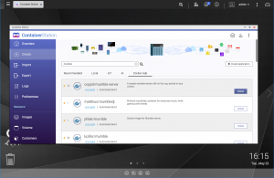
All done the system recognise the 16GB of RAM, and the new i7-4790s

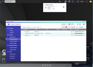
Time to put everything back, make sure you put the drives back in the right order. The device should boot and show all the changes in the System Status.

Here is the comparison of the i7-4790s with 16GB RAM vs i3-4150 with 4GB RAM.
https://browser.geekbench.com/v5/cpu/compare/2793185?baseline=2770826

https://browser.geekbench.com/v4/cpu/compare/15605085?baseline=15601418

This upgrade has given the device double the performance and the needed RAM for memory intensive applications. Though the whole process will take a very long time, it has taken me 4 hours, but I was taking photos and making everything visible for this guide. I wish you luck, I cannot be held responsible of damaging your device when following this guide.
Hi, Just wanted to leave a message to say thank you for the time you put in to this guide.
I’ve been rocking a 671 since 2015 and have just got round to fitting a i7-4790s, using your guide made it an easy upgrade.
Good luck in this new year and again Thank you.
Thank you Dave for the message, 😀 it’s great to hear that people still uses the tutorial and help extend their usage for their own device.
Have a great new year too with your faster QNAP, slap on 32GB RAM you kinda maxed out for awhile. Enjoy!
Thank you very much, I am from China, according to your guide, my TVS-471 changed the CPU and upgraded from i3-4150 to E3-1265L v3
Thanks Jason, glad that the guide is useful, with the higher spec CPU you’re going to have extra years of usage 😀
Thank you for this guide. I just used it to upgrade my QNAP TVS-671 from an i3 to i7 CPU. Of course there were some differences between your TVS-871 guide an my TVS-671 but it provided all the major steps I needed to follow. Overall, it took me about 1.5 hours and everything seems to be working properly. Thank you, again.
Didn’t took that long for you, the smaller chassis should have slightly different counter part. But I’m sure it isn’t that much different. But I got to say that this TVS-X71 series sure have lots of screws. Thanks for checking the guide
I also upgraded my tvs-671 with the i7 4790s using the instructions, only the 16gb RAM is the maximum is a pity. Thank you for the instructions.
Sorry for the late reply, but thank you for your message. It seems that the TVS-X71 series lives on
This is one of the best write ups I’ve ever seen on the Internet, thank you very much! In July 2019 I successfully upgraded a TVS-471 with the i7-4790T and now I am in the process of doing my TVS-871T with an i7-4790S. Re-reading this to refresh my memory. Thanks again! P.S. I see your January 9 comment talk about putting in 32GB but the beginning of the guide seems that 16GB is the maximum these will support… Is it possible to do 32GB? 🙂
You can check the memory support on the CPU specification page, most top end CPU for that generation can go 32GB RAM support. But I no longer have this device to even test it, it’s down to you guys to confirm. I assume it can, I only had 8GB RAM stick at the time.
Ryan did you ever get 32gb to work?
Thank you for this detailed and thought out how-to. I am about to upgrade my TVS-871 using what you noted here. Great read and the pictures were very helpful. I could only get an i7-4770s though but it looks fine and is 65W. $120AUD upgrade to go from i3 to i7 and 4GB to 16GB 🙂
Good that you’ve found the tutorial helpful, it’s getting cheap to upgrade these older system.